

High-Performance Cooling Products for Advanced Applications
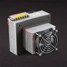
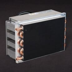
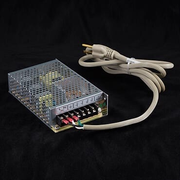
TE Technology offers the highest quality thermoelectric coolers for all of your cooling products needs. We design and manufacture thermoelectric cold plates, liquid coolers, and thermoelectric coolers for applications that demand extremely high reliability. We also provide a complete line of thermoelectric (Peltier) cooling modules, temperature controllers, Peltier coolers, and power supplies. Whether you need rapid delivery of a standard cooler, a Peltier heat sink, or the economy and flexibility of a custom solution, TE Technology delivers comprehensive thermoelectric Cooling Products and advanced cooling solutions.
Expert Engineering, Precision Manufacturing: Quality Thermal Solutions Delivered